Heathkit SB-230 tube retrofit

My amplifier
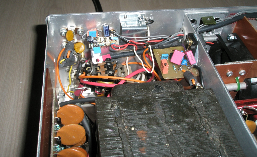
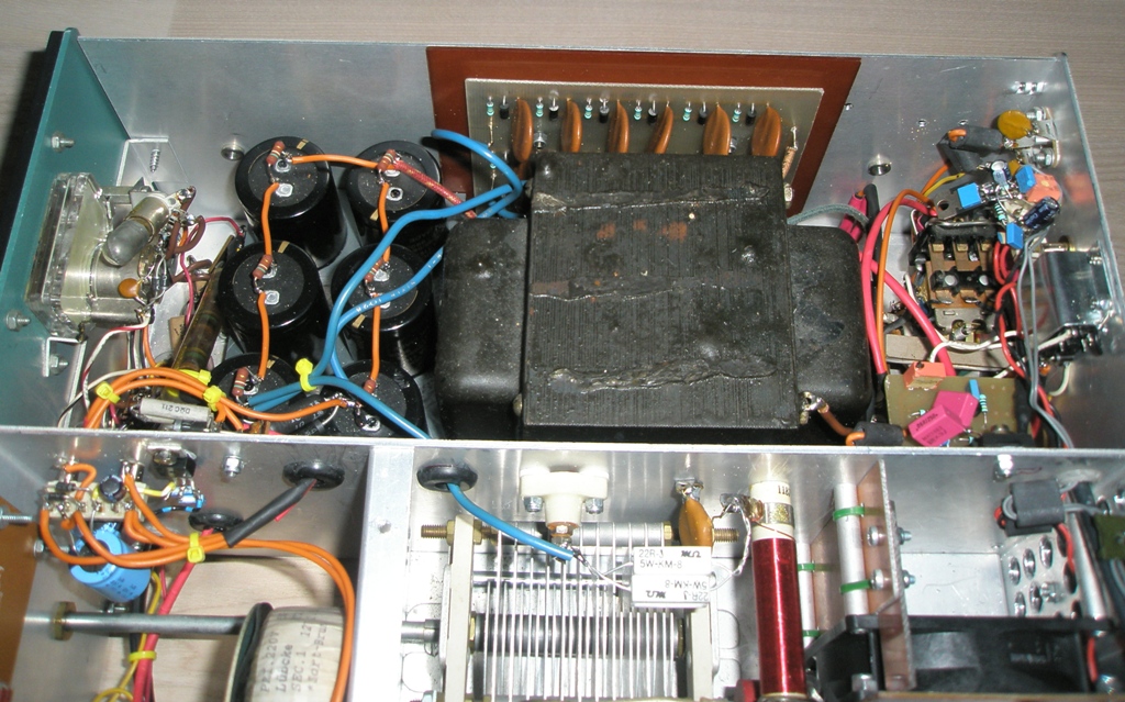
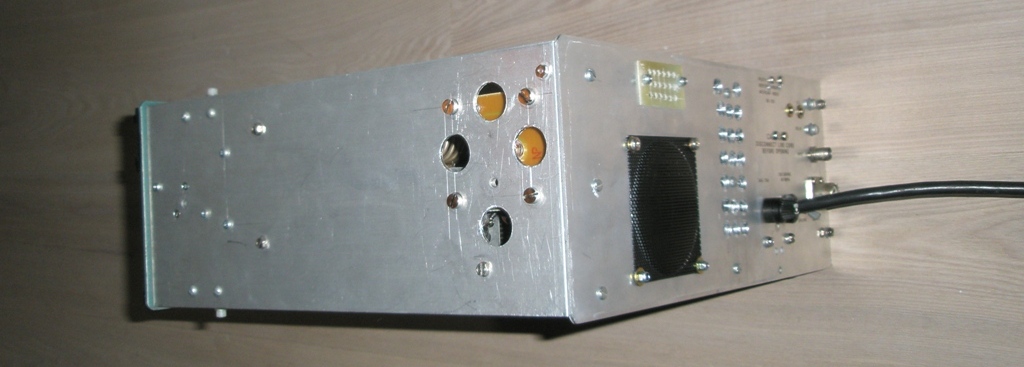
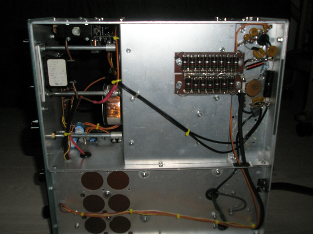
The first 2 pictures shows the original amplifier inside and from the back.
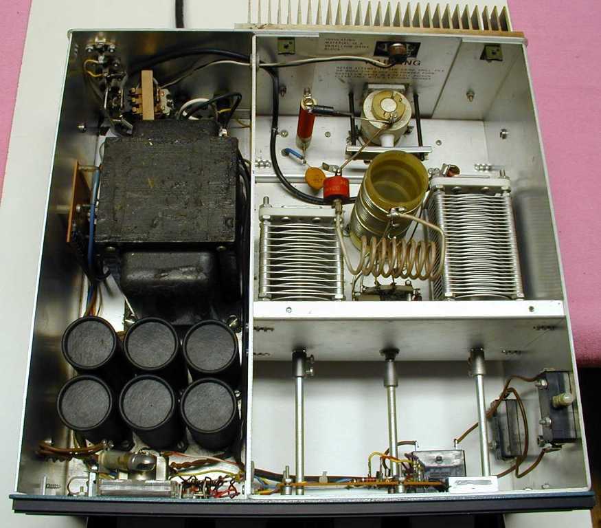
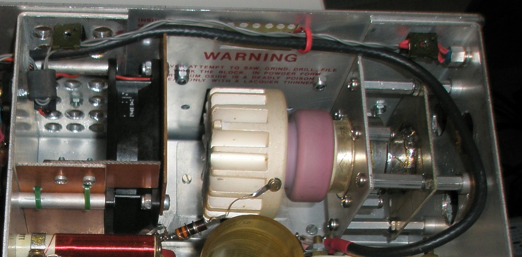
This is the original amplifier. The tube is a Eimac 8873 which is designed for conduction cooling. The tube is not produced any more.
Another issue is the highly toxic BeO heat transfer block - I am glad to get rid of it.
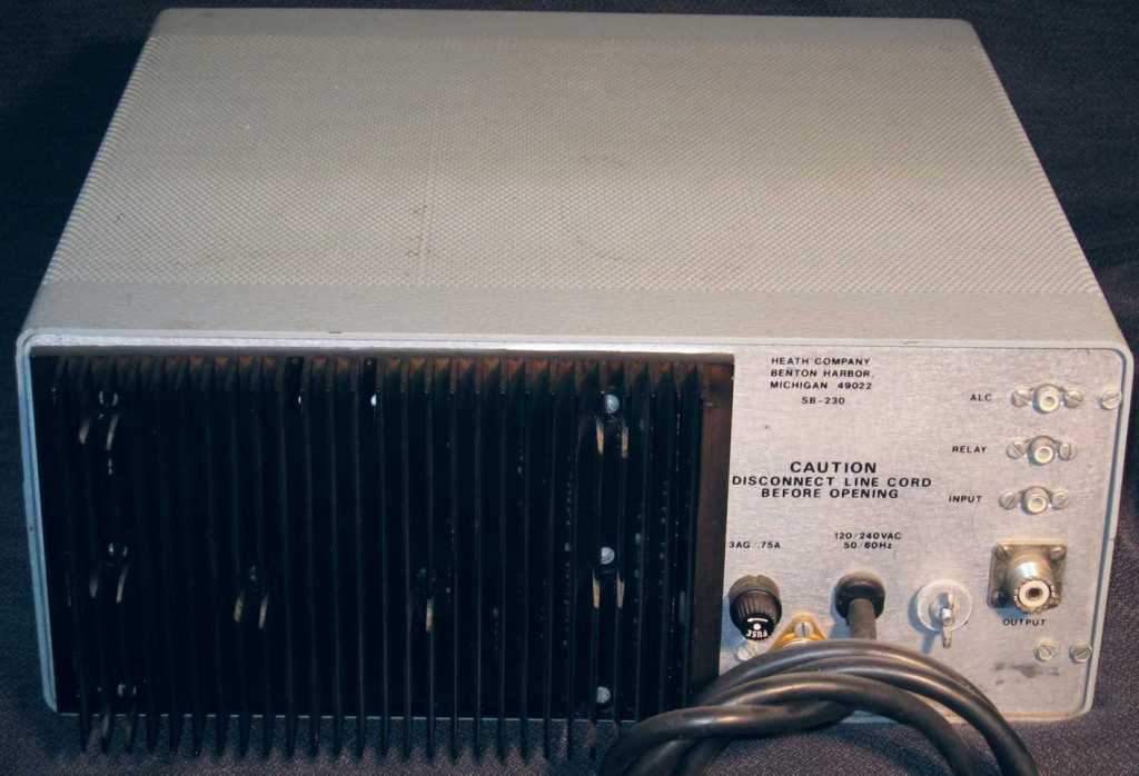
This is the original amp back side.
The way I did it:
I have decided to make new PCB's for the high voltage board and I have added a 2 sec. slow start delay and a temperature controlled fan circuit.The first version, without fan control, worked fine, but the PA became quite hot when simulating a contest (I let the CQ machine calling every 5 second during a longer period of time). I the decided to add a more efficient fan and add the fan control.
Tube used for this retrofit: GI-7BT
My retrofit is inspired from this page: http://www.wd8das.net/SB230.html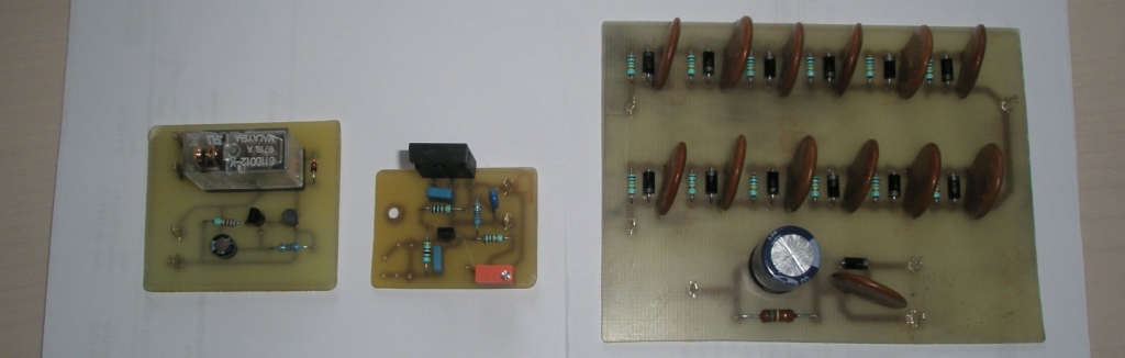
The 3 new PCB's. From left: 2 sec slow start, BIAS board and HV board. I decided to add capacitors and resistors across the diodes.
I know that this topic is discussed a lot of places and there are several opinions about this. I decided that the capacitor is a good idea to make sure that the diodes are RF passive. To make sure that the reverse voltage is as even as possible the resistors were added.
The 2 sec. slow start board is mounted. On the right side 2 resistors in parallel is inserted into the main supply and short circuited by the relay after 2 sec. A schematic will be added to this page later on.
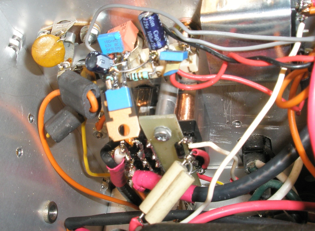
The BIAS board (taken from: http://bias.gs35b.com/docs/060923.html) on the right side. In the middle You see the fan controller.
A 4.7k NTC resistor is mounted close to the tube socket. See later picture.
The high voltage board seen in the middle of the picture. Below, left, the 12VDC supply is mounted.
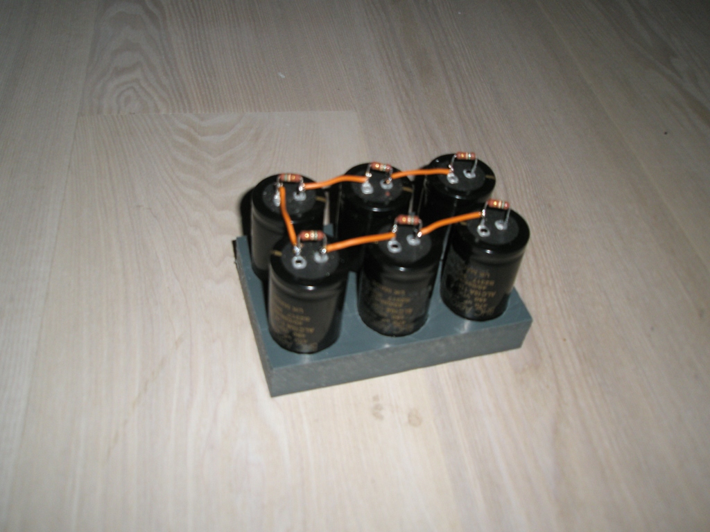
The new capacitors fitted into a peace of plastic material (don't know the type). These are 470µF instead of the old 125 µF types.
The new GI-7BT tube and the fan. This is the first version. Later on I decided to improve the cooling system.
The right side also contains a new filament transformer since the old tube did use 6.3V and the new one 12.6V.
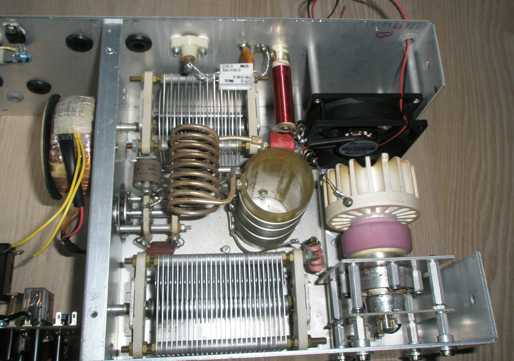
Cooling V.2. A more powerful fan was mounted. Some holes drilled and the air inlet optimized with peaces of PCB.
On the right side the NTC resistor is mounted.
Holes behind the socket to make sure that some airflow passes by.
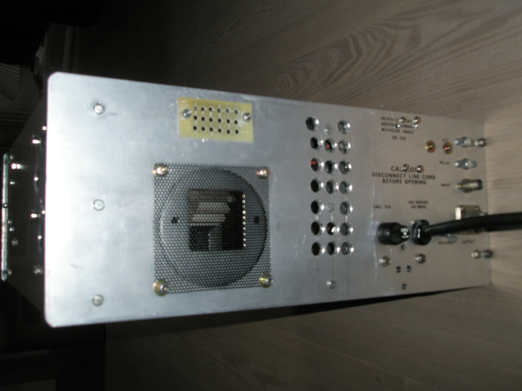
The back side of the PA. The old holes are covered to make sure noboby get hurt. The new holes are not covered since no potential danger is represented.
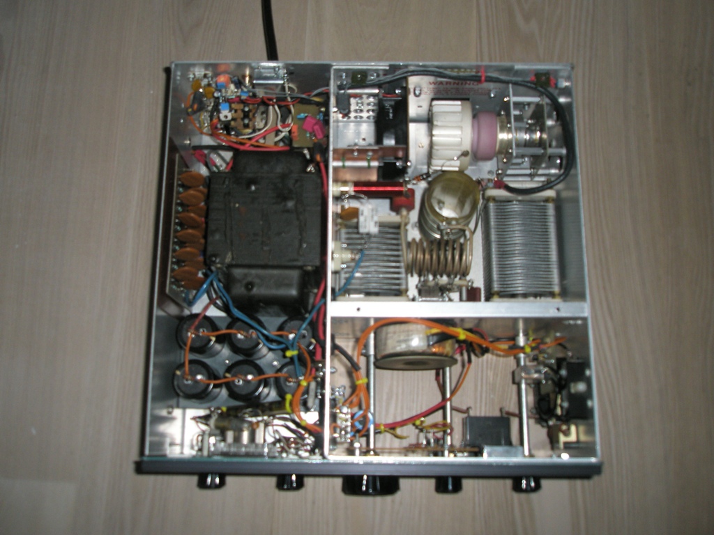
A top view of the PA.
Bottom View. There is almost nothing left since alll the HV parts are moved on the other side.
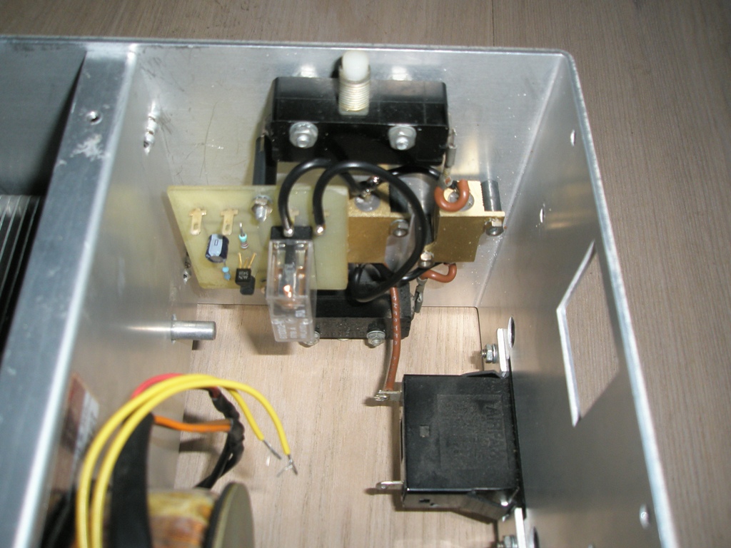
This evening the coil on the antenna relay died. Sparks were seen inside the coil. I decided not to rewind the coil and instead replace the relay.
I got some relays with big contacts and used 2 of them. The PA is up and running again.